Saturday, May 28, 2005

Controlling hardware with computers 101

A controller (e.g. Labjack) is needed to interface a computer to hardware (e.g. DC motor). A power source is needed for most controllers if the computer port has insufficient power.

The simplest way to control a DC motor is to use a transistor. To control the direction, use an H bridge. Use one of the computer's ports (USB, parallel port etc.) to communicate with the controller. To get feedback from the hardware, use a sensor (e.g. encoder that gives the position of the DC motor).

A controller will have one or more of the following -
  1. Counter - Keeps track (on an internal register) of voltage pulses (e.g. from an encoder). The computer can then query this register (e.g. to find out the position of a DC motor).
  2. Analog input - Converts a voltage level (e.g. from sensors that convert temp into voltage) into a digital value that can then read by the computer.
  3. Analog output - Converts the digital values from the computer to a voltage level which can be used to produce a variable output.
  4. Digital input - Each digital I/O can be configured to one of 3 states - input, output-high or output-low. If the voltage is higher than a threshold value, the computer will read the digital input as high/1, and if it is lower than another threshold value, the computer will read it as low/0.
  5. Digital output - If the computer instructs a high output, the output will produce a voltage (e.g. 5 volts), and if the computer instructs a low output, it produces no voltage.

Thursday, May 26, 2005

Controllers 101

Microcontroller
A microcontroller is a special purpose computer. There are microcontrollers inside TV's and cars. It has a [micro]processor inside. It can run programs (instead of using many gates).

Integrated Circuit
An IC is a thin chip containing many transistors and resistors. A microprocessor is an example of an IC.

Microprocessor
When the CPU (a CPU carries out instructions from software) is on a single IC it's called a Microprocessor. It has many transistors. It executes machine instructions to do 3 basic things -
  1. Using it's ALU perform math operations like addition etc.
  2. Move data from one memory location to another
  3. Make decisions and jump to new instructions based on those decisions

Assembly language
Assembly language is the native language of a microprocessor. A C program after being compiled is converted into assembly language.

Breadboard
Used to build a prototype of electronics. It's a piece of plastic with many holes that are linked with conductive traces in rows. The name is derived from early days when amateurs would nail copper wire to a wooden board (used for bread cutting) and solder electronic components to them.

Torque Control

Tuesday, May 24, 2005

Shopping List

  • DC Motor and Encoder - $50
  • H Bridge - $5
  • Labjack/NI DAQ - $100
  • Amplifier - $10
  • Decoder - $5
  • Motor Driver (for Torque Control)

Labjack Tracking# 1Z1A1E440344484277

Thursday, May 19, 2005

Servos 101

http://www.ee.ualberta.ca/~verret/ee401/servos101.htm

A servo is a motor that is attached to a position feedback device. Generally there is a circuit that allows the motor to be commanded to go to a specified "position". A very common use of servos is in Radio Controlled models. These R/C servos are sold at hobby stores and via mail order by places like Tower Hobbies for anywhere from $5 to $150.

R/C Servos come in standard "sizes" (so that they fit models well) and use similar control schemes. Unlike general purpose motors, R/C servos are constrained from full rotation. Instead they have a limited rotation of about 180 degrees or less. This is sometimes changed (see "Servo Modifications" below).

A typical R/C servo is the Futaba S148. This servo looks like a rectangular box with a motor shaft coming out of one end and a connector with three wires out of the other end. Attached to the motor shaft is usually (but not always) a "control horn". This is a plastic piece with holes in it for attaching push rods or other mechanical linkages to the servo. The three wires are V+, Control, and Ground. R/C servos typically run on 4.8v (four NiCd batteries) but they often work with voltages between 4 and 6 volts. The control line is used to position the servo. In an R/C model, this line it attached to the radio reciever, on robots it is usually attached to the processor.

R/C Servos are controlled by sending them a "pulse" of variable width. The parameters for this pulse are that it has a minimum width, a maximum width, and a repetition rate. These values are not "standard" but there are conventions that are generally accepted. The convention is that a pulse of approximately 1500 uS (1.5 mS) is the "neutral" point for the servo. Given the rotation constraints of the servo, neutral is defined to be the position where the servo has exactly the same amount of potential rotation in the counter clockwise direction as it does in the clockwise direction. It is important to note that different R/C servos will have different constraints on their rotation but they _all_ have a neutral position, and that position is always around 1500 uS.

These servos are "active" devices, meaning that when commanded to move they will actively hold their position. Thus, if a servo is commanded to the neutral position and an external force is present to push against the servo (presumably through the mechanical linkage) the servo will actively resist being moved out of that position. The maximum amount of force the servo can exert is the torque rating of the servo. The Futaba servo is rated around 40 oz/inches or 2.5 pounds of push at 1 inch away from from the shaft of the servo motor. Servos will not hold their position forever though, the position pulse must be repeated to instruct the servo to stay in position. The maximum amount of time that can pass before the servo will stop holding its position is the command repetition rate. Typical values for the command repetition rate are 20 - 30 mS. You can repeat the pulse more often than this, but not less often. When this timeout expires and there hasn't been another pulse the servo de-energizes the motor. In this state in can be pushed out of position and it will not return to the commanded position.

When the pulse sent to a servo is less than 1500 uS. the servo positions and holds its output shaft some number of degrees counterclockwise from the neutral point. When the pulse is wider than 1500 uS the opposite occurs. The minimal width and the maximum width of pulse that will command the servo to turn to a valid position are functions of each servo. Different brands, and even different servos of the same brand, will have different maximum and minimums. Generally the minimum pulse will be about 1000 uS wide and the maximum pulse will be 2000uS wide. However, these are just guidelines and should be checked on the servos you use. In particular if you attempt to command a servo past its maximum or minimum rotation it will use the maximum amount of current trying unsuccessfully to achieve that position.

Another parameter that varies from servo to servo is the slew rate. This is the time it takes for the servo to change from one position to another. The worst case slewing time is when the servo is holding at the minimum rotation and it is commanded to go to maximum rotation. This can take several seconds on very high torque servos. Typically it takes less than two seconds.

Servo Construction

Servos are constructed from three basic pieces, a motor, a feedback device, and a control board. In R/C servos the feedback device is typically a potentiometer (variable resistor). The motor, through a series of gears, turns the output shaft and the potentiometer simultaneously. The potentiometer is fed into the servo control circuit and when the control circuit detects that the position is correct, it stops the motor.

The typical R/C servo varies most in its internal mechanics from other servos and this is generally the difference between "good" and "lousy" servos. The servo mechanism subsystems are the motor, the gear train, the potentiometer, the electronics, and the output shaft bearing. The electronics are pretty much all the same and so not an issue. In the motor department however you can get smaller and larger motors which effect the overall size of the servo. "mini" servos are generally more expensive than "standard" servos in part for this reason.

The gears also vary from servo to servo. Inexpensive servos have plastic gears that will wear out after less than 100 hours of use. More expensive servos have metal gears which are much more durable.

The potentiometer is the feedback device and often the first thing to fail in my servos. If it gets dirty, or the contacts get oxidized, the servo will fail to work properly, sometimes by "jittering or hunting" since the feedback is inaccurate, or turning completely to one side and drawing lots of current since the servo doesn't know where its output shaft is pointing. More expensive servos have "sealed" potentiometers, cheaper ones do not. I've found I can extend the life a wee bit of my pots by using some judicious application of silicone sealant around the edge. You can do this with a syringe if your careful. Be sure and not to get it on the gears though as it will cause them to bind.

The last subsystem is the output shaft bearing. Cheap servos invariably have a plastic on plastic bearing that will not take much load. Medium priced servos generally have metal on metal bearings that stand up better under extended use and expensive servos have ball bearings which work best. Many places also sell "ball bearing upgrades" for cheap servos which consist of a new top cover and ball based bearing for the output shaft. Tower Hobbies sells three "standard" servos with the part numbers TS-51, TS-55, and TS-57 whose primary difference is the bearing. (I believe the '57 has metal gears as well as a ball bearings)

Servo Modifications

When used with robots, R/C servos can be employed as sensor pointers, leg lifters, steering wheel turners, etc. But without modification they can not be the main drive system. Since a servo is, at its heart, a DC gear motor with enough torque to move a small platform, servos are often modified to become drive motors.

Modifing a servo to be a drive motor can use one of two strategies, breaking the feedback loop, or lobotomy.

The most brutal way of modifying a servo is the full lobotomy. You open up a servo, remove the electronics, bringing out the power lines to the motor and remove the potentiometer or modify it so that it can rotate 360 degrees. What you are left with is a DC motor, a gear train, and an output shaft on which you can mount plastic pieces that can be used as wheel mounts. This gives you complete control of the mechanics, but you do have to have a motor driver circuit to drive the DC motor in the servo housing.

Breaking the feedback loop is generally the easier way to modify a servo since it takes advantage of the power switching circuit already present on the servo to turn the motor on and off. This modification involves removing/disabling the potentiometer and replacing it with a voltage divider that convinces the servo electronics that the servo is in the neutral position. (You can figure this out by using the old pot, turned to the neutral position and measuring the resistance.) Now to turn the motor clockwise you send the servo a pulse that is wider than 1500 uS and the motor turns (and never stops because there is no potentiometer to tell the servo circuit it has gone far enough). Or to turn the motor counter- clockwise you send it a pulse less than 1500 uS wide.

This latter technique is fine except that the motor driver circuit in the servo may not be able to handle driving the motor continuously. In normal operation, the motor would be driven for a moment and then idled when the servo reached its position. The intermittent nature of turning the motor on and off allows the servo to use a motor driver that is smaller than one that would be needed for 100% duty cycle operation. If this turns out to be the case, the motor electronics will eventually burn out and you'll end up with the full lobotomy case by default.

--Chuck McManis
Wednesday, May 18, 2005

Hard Disk Motors

http://www.pcguide.com/ref/hdd/op/spin.htm

All PC hard disks use servo-controlled DC spindle motors. A servo system is a closed-loop feedback system; this is the exact same technology as is used in modern voice coil actuators, and I discuss how servo systems work in detail in that section. In the case of the spindle motor, the feedback for the closed-loop system comes in the form of a speed sensor. This provides the feedback information to the motor that allows it to spin at exactly the right speed.

  • Old Hard drives used a stepper Motor
  • Stepper motors are also commonly used for both turning the spindle and positioning the head on floppy disk drives. If you have a floppy drive, find one of its motors and turn it slowly with your hand; you will feel the discrete step-wise nature of its motion
  • The actuator in a modern hard disk uses a device called a voice coil

PHANTOM Mechanics

In its simplest form, the PHANTOM can be thought of as a transmission between three DC brushed motors with encoders and the human finger. The x, y and z coordinates of the user’s finger tip are tracked with the encoders, and the motors control the x, y and z forces exerted upon the user. Torques from the motors are transmitted through pre-tensioned cable reductions to a stiff, lightweight aluminum linkage. At the end of this linkage is a passive, three degrees of freedom gimbal attached to a thimble. Because the three passive rotational axes of the gimbal coincide at a point, there can be no torque about that point, only a pure force. This allows the user’s finger tip to assume any comfortable orientation. More importantly, because the user can be represented by a single point of friction-less sphere within the virtual environment, collisions and resulting interaction forces within the virtual environment are easily calculated.

The PHANTOM has been designed so that the transformation matrix between motor rotations and endpoint translations is nearly diagonal. Decoupling the three motors produces desirable results in terms of back-drive friction and inertia. For a haptic interface with perceivable inertia and back-drive friction, it is important that the friction and inertia be nearly constant in all directions to minimize the distraction they create for the user (i.e. well conditioned inertia matrix and small, non-disparate friction components) (Vertut, 1986). As interesting design feature of the PHANTOM is that two of the three motors move in such a manner as to counterbalance the linkage structure. Because the PHANTOM is statistically balanced, there is no need to compromise the dynamic range of the device by actively balancing the structure with biased the motor torques. Conveniently, the first rotational axis of the PHANTOM is located directly above the wrist of the user. This permits aligning the inherently spherical workspace of the mechanism with similarly spherical wrist. The complexity of the cable reduction mechanism is minimized by using a single cable to "mesh" two motor capstans with another pulley. This minimizes mechanism width and tensioning difficulty.

http://www.cs.ubc.ca/labs/spin/publications/related/massie94.pdf

Motors 101

Types of Motors -
  • AC Motors - simply a series of three windings in the exterior (stator) section with a simple rotating section (rotor). The changing field caused by the 50 or 60 Hertz AC line voltage causes the rotor to rotate around the axis of the motor. Cheap e.g. for air conditioners with constant speed. Expensive to control.
  • DC Motors - Brushes change direction of current and the electromagnetic forces due to the current against the magnetic forces of the magnet + inertia keeps the coil moving.
  • Brushless DC Motors -
  • Servo Motors - Consists of a DC motor, a feedback device, and a control board. When given a position command it will actively hold that position and resist movement equal to its torque capacity. In R/C servos the feedback device is a potentiometer (variable resistor). The motor, through a series of gears, turns the output shaft and the potentiometer simultaneously. The potentiometer is fed into the servo control circuit and when the control circuit detects that the position is correct, it stops the motor.
  • Brushed DC Servo Motors -
  • Brushless AC Servo Motors -
  • Stepper Motors - Picture four coils with a magnet in the center. There are 2 current sources, each going to opposite coils. By varying the direction of flow of the current, it is possible to manipulate the direction of the movement of the center magnet, as well as control its rotational speed.
  • Linear Motors -

Good intro to motors -
http://www.ee.ualberta.ca/~verret/ee401/motors.htm


  • In a brushed DC motor, torque control is also simple, since output torque is proportional to current. If you limit the current, you have just limited the torque which the motor can achieve. This makes this motor ideal for delicate applications such as textile manufacturing.
http://www.oddparts.com/acsi/motortut.htm


A drive is the power electronics board which is used to control the speed of a motor. Drives may use various techniques to control speed.

A low-cost form of drive for controlling DC motors makes use of a special type of power transistor called an SCR. Hence the term SCR drive .

An SCR acts as a gate to allow a precise amount of current to flow to the motor. Through feedback systems, this current also controls the voltage allowed to generate the armature field of the motor, and thus the speed is controlled.

SCR drives are most commonly used to control DC motors, but the system is also used in some older AC inverter drives controlling AC motors


http://www.iea.lth.se/sed - good class notes on Torque Control

http://www.mskennedy.com/media/documents/Motor.pdf

Tuesday, May 17, 2005

Controlling a DC Motor

Small DC motors are easy to model and control. Fortunately for us, they can be reduced to simple terms so our control algorithms are easy to code. The permanent magnet DC motor can be modeled as a device that produces torque proportional to the current flowing through it. It also produced a voltage proportional to the rotational velocity. One last bit of modeling completes the picture: there is a small series resistance in the model. Hence, if one stalls a motor, the current draw and torque produced will be the supply voltage divided by the resistance.

Commonly one reads that the RPM of a motor is proportional to the voltage across it’s terminals – and for most purposes that is true: at any given voltage, the motor will spin up in speed until the generator portion of the motor model matches the supply voltage. At that point no more current will flow into the motor and it will produce zero torque. Of course, there is some amount of friction, so there will be some amount of torque required to spin the motor, thus some amount of current needed. This current causes a voltage drop across the small series resistance in our motor model. This voltage drop takes away from supply voltage and causes the motor to spin a bit slower than the supply voltage would indicate.

In industrial controllers one typically sees a variety of control methods: constant speed, where the applied voltage is "adjusted" for the IR voltage drop across the internal resistance (the controller measures the current though the motor, calculates the voltage drop across the internal resistance and bumps the supply voltage to compensate); Constant torque, which is simply a constant current supply, and the incremental encoder or tachometer feedback systems which, of course, give absolute control over position and speed.

This is from - http://www.barello.net/Papers/Motion_Control

Monday, May 16, 2005

USB Servo Control

This is along the right direction -

http://www.phidgetsusa.com/tutorials/tutorial_Servor_Controller.asp

This lets you control a basic Servo using C++ and plugs into your USB port. I'm going to order the following -

Product: Servo 1-Motor
Product ID: 1000Price: $25.25 US
Description: Phidget USB Servo Controller
This controls a single servo motor and needs no additional power supply.
Packaged with a 6 foot USB cable.

Product: Hitec Servo - HS422
Product ID: 9SHS422
Price: $12.49 US
Description: Servo
Stall Torque (4.8V): 45.82 oz/in. (3.3kg.cm)
Stall Torque (6.0V): 56.93 oz/in. (4.1kg.cm)
Current Drain (4.8V): 8mA/idle and 150mA no load operating
Current Drain (6.0V): 8.8mA/idle and 180mA no load operating
Connector Wire Length: 11.81" (300mm)
Dimensions: 1.59" x 0.77"x 1.44" (40.6 x 19.8 x 36.6mm)Weight: 1.6oz (45.5g)

I ordered these two - here's the shipping info.

Rotary Encoders 101

Definition

An encoder is an electrical mechanical device that can monitor motion or position

tutorial on encoders

Interfacing a rotary encoder to a PC


http://www.heidenhain.com/programmable.html

Parts needed

There are four basic parts that are needed for this system -
  • Motor (to apply torque and apply tension on the string)
  • Rotary encoder (to measure length of string)
  • A stiff string
  • A controller board (to control the torque with a computer)
The goal is to build the system as cheaply as possible. I called maxonmotors and just the motor and encoder cost $155 each! My goal is less than $100. Possibilites are -

Motor and encoder
  1. Scavenged disk drive actuators

String

  1. Fishing cables
  2. Guitar strings
Controller
  1. Make your own board and connect it to your parallel port
This circuit has proven useful when interfacing my computer to home made robotics. It is easy to build and use and it can control two DC motors of any current or voltage rating, depending on the rating of the relays. The circuit also provides two shaft encoders for positional feedback to the computer.
Electronics Australia, October 1994, pp.51

Hacking GLUT

Here's a great website and a lifesaver -

http://sjbaker.org/steve/software/glut_hack.html

I repost the article here in case his server ever goes offline -

Hacking GLUT to Eliminate the glutMainLoop() Problem

Mark Kilgard's GLUT library is one of the most truly useful aids to portable programming. It carefully hides all the ugly issues of window manipulation, producing simple menu's, keboard, mouse and joystick I/O. If your application can tolerate the restrictions of GLUT, it's a breeze to write code that will port across dozens of dissimilar platforms.

There has to be a 'BUT'...

Yep - there certainly is. GLUT is a strictly event driven library. Essentially, all GLUT applications must set up callbacks for all the events they are interested in (Keystrokes, redisplay, resize, mouse clicks, etc) - and then hand over control to a GLUT function called 'glutMainLoop()' - which never returns. That's fine for simple programs that don't use certain other libraries - but now and again, you'll want to link a GLUT program to another library that ALSO assumes control of the main loop. Another time this can be a pain is if you want to retro-fit a simple user interface into an existing, complex application which might not be able to use the glutIdleFunc callback.

This turns off a lot of users and IMHO is an unnecessary restriction.
So What Can I do About It?
There are several ways to get around the problem of needing another library that also wants to 'own' the main loop.
  • You could attack the OTHER library and try to remove its main-loop restriction. That isn't always possible - and if you don't have the sources to the other library then you've had it.
  • You could try to create multiple execution threads - one for GLUT's main loop, another for the other library. That won't work in all operating systems - and some libraries are not at all thread-safe. This sometimes works well though.
  • You can hack GLUT.
The last option is really the reason for this Web page. I have found that a dozen lines of code is all that's required and the resulting hacked GLUT remains 100% compatible with the original library.

What Do I Do?

Locate the GLUT source code. In every release I have examined, there will be a file named lib/glut/glut_event.c

Inside that file you'll find the source for glutMainLoop(). In outline it looks like this:

/* CENTRY */
void APIENTRY
glutMainLoop(void)
{


for (;;) {

}
}
/* ENDCENTRY */

This may be changed to look like this:

/* CENTRY */
void APIENTRY
glutMainLoop(void)
{
for(;;)
glutMainLoopUpdate () ;
}
/* ENDCENTRY */

/* CENTRY */
void APIENTRY
glutMainLoopUpdate(void)
{


}
/* ENDCENTRY */

You'll have to add a declaration for glutMainLoopUpdate() into glut.h:

extern void APIENTRY glutMainLoop(void);
extern void APIENTRY glutMainLoopUpdate(void);

Recompile...and that's it.

How Do I Use It?

Now, your code can change from:

glutMainLoop () ;

...to...

while ( 1 )
glutMainLoopUpdate () ;

But more usefully, you can now use one of the callbacks of some other library to call the new glutMainLoopUpdate() function:

some_other_library_IdleFunc ( glutMainLoopUpdate ) ;
some_other_library_MainLoop () ;

Is this Reliable?

It certainly seems to be - I know of dozens of people who have used this hack (or something very close to it) without any problems. All current GLUT implementations can be fixed in the exact same way.

It does have a microscopic effect on performance because the error checking that glutMainLoop() used to do only once is now done in every iteration of glutMainLoopUpdate(). However, in all current GLUT releases, the amount of checking is truly negligable - so this should not be a concern. If it worries you then dump the error checking code - it's not checking for anything too subtle - just making sure you called glutInit and opened a window.

Will This Become a Part of the Normal GLUT Release?

Well, I begin to doubt it. It seems a simple enough change - and there is no doubt that people find it useful. However, I have now asked Mark Kilgard to include it in the release on several occasions. He refuses on grounds of unnecessary complexity - I don't understand that view - but GLUT is his baby and he has the right to release whatever he wants.

IMPORTANT NOTE:


The information in this document has been obsoleted by the arrival on the scene of the freeglut library. freeglut has the 'hack' described below included as a standard part of the library, and additionally is released under a clear OpenSource license (the Xfree license) so it can be modified and redistributed without strings attached. freeglut is a superset of the GLUT functionality and can be linked with existing GLUT applications without modifications or recompiling.

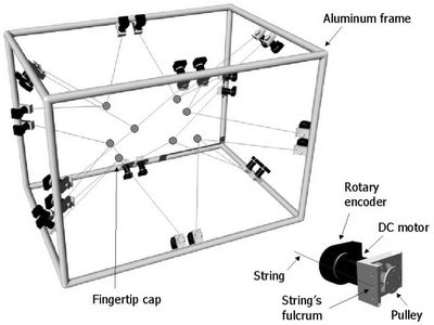
Setup of the device

Fingertip attachment

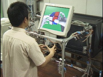
spidar demonstration at Tokyo Institute of Technology

Building Haptic Devices

Motors and Controllers

http://www.maxonmotor.com

RE-max24 motor 6.5W 24V No.220432 + No.201937 encorder
(for small (desktop) application)

USA (West Coast)
maxon precision motors inc.
838 Mitten Road
Burlingame, CA 94010

Phone: +1 650 - 697 9614
Fax: +1 650 - 697 2887
Internet: http://www.maxonmotorusa.com
Email: info@maxonmotorusa.com

I called (Sally - ext 1242) and found out that the pricing on these things -

Motor (220432)
Standard program - 21 in stock, will take 2weeks
$76.60 each

Encoder (201937)
6-8 weeks for encoder
$77.25 each

Total - $153.85 (motor+encoder)